Overhead Crane Runway Beam Design Guide | Loads, Standards & Best Practices
Designing an overhead crane runway beam is a critical part of any lifting system project. A well-designed runway beam ensures safe crane operation, long service life, and compliance with international standards. This guide explains the key design considerations, load calculations, structural requirements, and best practices for overhead crane runway beams—ideal for engineers, contractors, and industrial facility owners.
For warehouse lifting solutions, a 5 ton overhead crane for warehouse is a cost-effective option for most industrial facilities.
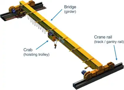
What Is an Overhead Crane Runway Beam?
An overhead crane runway beam is the structural beam that supports the crane rails. It transfers crane loads—including lifted loads, trolley weight, and dynamic forces—into columns or building structures.
Runway beams are typically fabricated from:
-
Rolled steel I-beams
-
Welded plate girders
-
Box girders (for heavy-duty cranes)
They are widely used in factories, warehouses, steel plants, and power stations.
Key Loads in Runway Beam Design
Accurate load calculation is the foundation of safe runway beam design. The following loads must be considered:
1. Vertical Loads
-
Crane self-weight
-
Hoist and trolley weight
-
Rated lifting load
-
Impact factor (dynamic load amplification)
2. Horizontal Loads
-
Longitudinal forces from crane acceleration and braking
-
Transverse forces due to trolley movement and skewing
3. Lateral Loads
-
Rail misalignment
-
Crane surge and side thrust
Design codes usually require applying a percentage of the lifted load as horizontal force to account for these effects.
Structural Design Considerations
Beam Strength and Deflection
-
Bending stress must remain within allowable limits
-
Vertical deflection is typically limited to L/600 ~ L/750
-
Excessive deflection can cause rail misalignment and crane wear
Fatigue Design
Runway beams are subject to repeated loading cycles. Fatigue checks are essential, especially for:
-
High-duty cranes
-
Continuous production lines
-
Heavy lifting applications
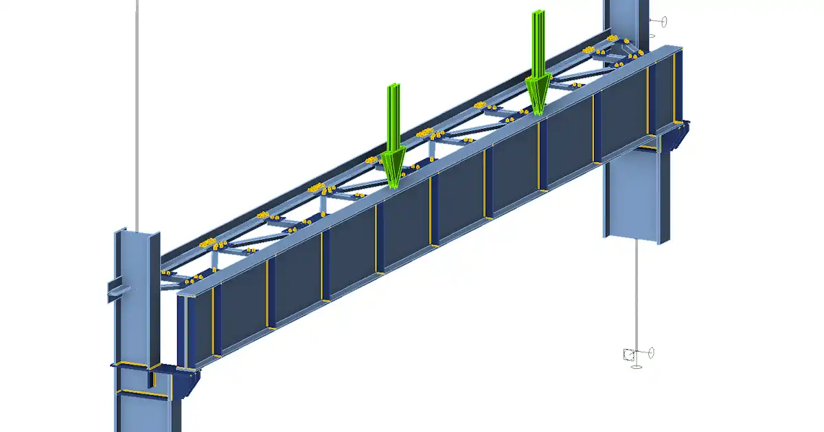
Local Wheel Load Effects
Crane wheel loads cause high local stresses at the top flange. Designers often reinforce the beam using:
-
Flange plates
-
Stiffeners
-
Cap channels
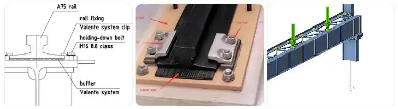
Crane Rail and Connection Design
The runway beam works together with the crane rail system:
-
Rails are fixed using clips, bolts, or welded pads
-
Allowance must be made for thermal expansion
-
Rail alignment tolerance is critical for smooth crane travel
Improper rail installation can lead to wheel wear, vibration, and structural fatigue.
Common Design Standards
Runway beam design typically follows recognized international standards, such as:
-
CMAA specifications
-
AISC steel design codes
-
FEM crane classification rules
The selected standard depends on project location and crane duty classification.
Best Practices for Overhead Crane Runway Beams
-
Coordinate crane supplier data early in the design stage
-
Verify load combinations with structural and crane engineers
-
Ensure proper corrosion protection (painting or galvanizing)
-
Perform regular inspection and alignment checks after installation
A properly designed runway beam reduces maintenance costs and improves crane safety over its entire lifecycle.
An effective overhead crane runway beam design balances strength, stiffness, fatigue resistance, and constructability. By understanding load paths, structural behavior, and applicable standards, engineers can deliver safe and reliable crane systems for industrial operations.
If you are planning a new crane installation or upgrading an existing facility, investing in correct runway beam design is essential for long-term performance and compliance.
