450t-38m gantry crane overall design, lifting, moving and traveling mechanism design
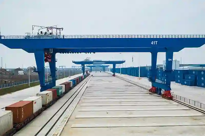
The 450-ton crane designed in this article is used in the concrete beam manufacturing yard of high-speed railway projects. The concrete box beams manufactured in the beam yard have a mass of 900 tons and are usually jointly hoisted by two 450 ton gantry cranes across the railway line. This crane can be used to assemble a bridge crane.

The layout of the beam yard is different from the main operation mode, and the span and lifting height of the crane are also different. In order to meet different requirements, the structural form is also different. The main beam of this type of crane mostly adopts a box-shaped double beam, and the outrigger adopts an A-shaped structure, which is rigidly connected to the main beam. In order to improve the force distribution of the outrigger, the connection between the outrigger and the main beam also adopts a structure with one side rigid and the other side flexible.
1.Overall design parameters
- The whole machine working level: A3 (U1, Q4), suitable for medium-frequency and medium-load operation scenarios.
- Lifting capacity: 450 tons, meeting the lifting needs of large components.
- Span: 38 meters, adapting to the operation requirements of different sites.
- Maximum lifting height: 29 meters, meeting the needs of high-rise operations.
- Lifting speed: 0-0.5m/min for heavy load, 0-1.0m/min for no-load, ensuring operation safety and efficiency.
- Cart running speed: 0-5m/min for heavy load, 0-10m/min for no-load, adapting to the speed requirements of different operation scenarios.
- Trolley running speed: 0-2m/min for heavy load, 0-6m/min for no-load, improving operation flexibility.
- Cart working level: M3, adapting to medium-frequency car operation.
- Trolley working level: M3, adapting to medium-frequency trolley operation.
- Lifting working level: M4, adapting to higher-frequency lifting operations.
- Metal structure working level: E3 (B2, S4), ensuring the long-term stability of the metal structure.
2. Design of lifting mechanism

Wire rope selection:
Select the appropriate wire rope diameter, strength and type according to the lifting weight, lifting speed and working environment.Consider the wear resistance, corrosion resistance and breaking tension of the wire rope to ensure safe operation.
Drum design:
Determine the geometric dimensions of the drum to ensure that the drum has sufficient strength and rigidity to withstand the tension of the wire rope.Design a reasonable wire rope fixing method to prevent the wire rope from falling off or loosening.
Motor selection:
Select the appropriate motor type, power and speed according to the power requirements of the lifting mechanism.Perform heat verification of the motor to ensure that the motor will not overheat under continuous working conditions.
Reducer selection:
Select the appropriate reducer type and transmission ratio according to the motor speed and lifting speed requirements.Ensure that the reducer has sufficient load-bearing capacity and transmission efficiency.
Brake selection:
Use a normally closed brake to ensure that the lifting mechanism can brake quickly in the event of a power outage or failure.Set up an automatic wear compensation device and a manual release device to improve the reliability and service life of the brake.
Mechanism starting time calculation:
Calculate the starting time of the lifting mechanism according to the starting torque and load torque of the motor.Ensure that the starting time is within a reasonable range to avoid excessive impact on the power grid and mechanical equipment.
3. Operating mechanism design
Operation static resistance calculation:
Considering the dead weight, load, track slope and other factors of the crane, calculate the resistance of the operating mechanism in a static state.Provide a basis for the selection of motors and the design of transmission systems.
Motor selection and calculation:
Select the appropriate motor type, power and speed according to the power requirements and operating speed requirements of the operating mechanism.Perform motor heating verification and overload capacity verification to ensure that the motor can work normally under various working conditions.
Reducer selection and calculation:
Select the appropriate reducer type and transmission ratio according to the motor speed and operating speed requirements.Perform reducer load capacity verification and transmission efficiency calculation to ensure that the reducer can meet the needs of the operating mechanism.
Coupling selection:
Select the appropriate coupling type and specification according to the shaft diameter and speed of the motor and reducer.Ensure that the coupling has sufficient load-bearing capacity and transmission efficiency, and can compensate for certain axial and radial displacements.
Brake selection:
Use electromagnetic disk brakes or hydraulic failure protection brakes to ensure that the operating mechanism can brake quickly in the event of power outages or failures.Set up automatic wear compensation devices and manual release devices for the brakes to improve the reliability and service life of the brakes.
Wheel strength calculation:
Calculate the strength and stiffness of the wheels based on factors such as the crane's deadweight, load and operating speed.Ensure that the wheels have sufficient load-bearing capacity and wear resistance, and can adapt to the operating requirements of different tracks.
4. Travel mechanism design

Trolley travel mechanism design:
A double-track travel scheme is adopted, consisting of 8 double-track travel trolleys to ensure the stability and safety of the trolley travel.Each double-track travel trolley consists of a trolley frame, a wheel group, an electric motor and a reducer, and is driven by a variable frequency motor to achieve stepless speed regulation.
A trolley travel correction device is set up to ensure that the travel distance deviation between the rigid outrigger and the flexible outrigger is controlled within the allowable range.
Design of the trolley travel mechanism:
The trolley travel mechanism consists of four active trolleys and four passive trolleys. Each active trolley consists of two running wheels, a variable frequency motor and a reducer.The variable frequency speed regulation technology is adopted to achieve stepless speed regulation and smooth operation of the trolley.
The trolley travel limit device and buffer are set to prevent the trolley from running beyond the track range or collision accidents.
 |
 |